A crucial equipment for any electronics enthusiast besides multimeter,soldering iron,etc is an Oscilloscope. Unfortunately these oscilloscopes come at a price which students or hobbyists couldn’t afford.
Here, a low frequency oscilloscope is designed using TI’s MSP430G2231 microcontroller. The frequency range it could measure is few Khz but that is sufficient for most circuits testing since they operate on low frequencies.

Components used:
- MSP430G2231 microcontroller
- MSP430 Launchpad
- 3.3V Voltage regulator *
- USB-Serial Converter *
- BC547 transistors *
- Switches *
- LEDS *
- Connectors,General Purpose board,wires,etc *
* – Optional
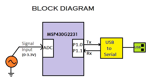
I have made the entire circuit in a stand-alone pcb here. This can be very well implemented with Launchpad alone since it has everything onboard.The overall block diagram is given below.

The input signal should have the voltage range of 0-3.3V since anything out of this range is dangerous to msp430. Now the input is sampled at a high frequency using the built in ADC of MSP430G2231. The digital data output is of 10-bit length and is right shifted twice to downscale into an 8-bit data.
This 8-bit data is packetized and sent to the serial port using GPIO pin P1.0. Since MSP430G2231 doesn’t have hardware UART, software UART is implemented using bit-banging.An alternative way would be using higher series of msp430 like MSP430G2553 which has built in UART.

This data is received by host side GUI application written in MATLAB and the graph is plotted in real time. The following is a snapshot of a 90% duty cycle waveform generated from another micrcontroller which is received by the oscilloscope circuit and is plotted in PC by MATLAB.

We can choose the COM port number to which the serial port is connected. Start button will initiate the data reception sequence from MSP430G2231. RMS voltage is computed from 100 data samples received and is displayed along with the waveform.
Author Profile
Latest entries
 ElectronicsMarch 3, 2019Sipeed Maix Bit, a 64-bit dual core RISC-V AI development board
 ElectronicsFebruary 18, 2017Building a 49cc Street Legal Motorized Bicycle
 ElectronicsDecember 28, 2016Programming STM32 ARM microcontrollers in Arch Linux
 ElectronicsMay 17, 2016ESP8266 – WiFi + Speech Controlled Hexapod Robot


